- 您现在的位置:买卖IC网 > Sheet目录475 > MAX9993ETP+D (Maxim Integrated)IC MIXER DOWN CONV 20-TQFN
High-Linearity 1700MHz to 2200MHz Down-
Conversion Mixer with LO Buffer/Switch
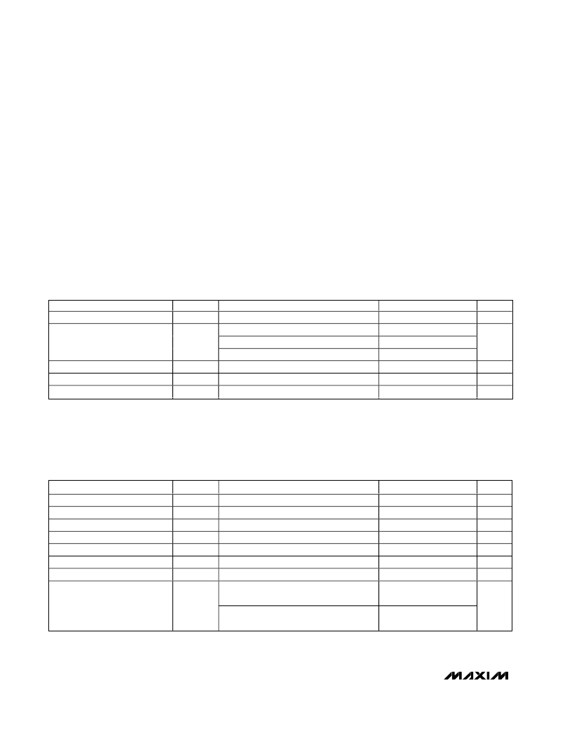
ABSOLUTE MAXIMUM RATINGS
V CC ..........................................................................-0.3V to 5.5V
RF (RF is DC shorted to GND through balun).....................50mA
LO1, LO2 to GND ...............................................................±0.3V
TAP, IF+, IF- to GND ..................................-0.3V to (V CC + 0.3V)
LOSEL to GND ................................-0.3V to (V CC (pin 8) + 0.3V)
LOBIAS, IFBIAS, LEXT to GND ..................-0.3V to (V CC + 0.3V)
RF and LO Input Power ..................................................+22dBm
Continuous Power Dissipation (T A = +70 ° C)
20-Lead Thin QFN
(derate 30.3mW/ ° C above T A = +70 ° C) ....................2200mW
θ JA ....................................................................................33 ° C/W
Operating Temperature Range ...........................-40 ° C to +85 ° C
Storage Temperature Range .............................-65 ° C to +150 ° C
Lead Temperature (soldering, 10s) .................................+300 ° C
Stresses beyond those listed under “Absolute Maximum Ratings” may cause permanent damage to the device. These are stress ratings only, and functional
operation of the device at these or any other conditions beyond those indicated in the operational sections of the specifications is not implied. Exposure to
absolute maximum rating conditions for extended periods may affect device reliability.
DC ELECTRICAL CHARACTERISTICS
( Typical Operating Circuit as shown, no input RF or LO signals applied. V CC = 4.75V to 5.25V, T A = -40 ° C to +85 ° C. Typical values are
at V CC = 5.0V and T A = +25 ° C, unless otherwise noted.)
PARAMETER
Supply Voltage
SYMBOL
V CC
CONDITIONS
MIN
4.75
TYP
5.00
MAX
5.25
UNITS
V
Total supply current
202
230
Supply Current
I CC
V CC (pin 8)
87
105
mA
IF+/IF- (total of both)
103
133
LOSEL Input High Voltage
LOSEL Input Low Voltage
V IH
V IL
2.0
0.8
V
V
LOSEL Input Current
I IL and I IH
-5
+5
μA
AC ELECTRICAL CHARACTERISTICS
( Typical Operating Circuit , 4.75V < V CC < 5.75V, -40 ° C < T A < +85 ° , RF and LO ports are driven from 50 ? sources, 0dBm < P LO <
+6dBm, P RF = -5dBm, 1700MHz < f RF < 2200MHz, 1400MHz < f LO < 2000MHz, f IF = 200MHz. Typical values are for T A = +25 ° C
V CC = 5.0V, P LO = +3dBm, f RF = 1900MHz, f LO = 1700MHz, 200MHz IF.) (Notes 1, 2)
PARAMETER
RF Frequency
LO Frequency
SYMBOL
f RF
f LO
(Note 6)
CONDITIONS
MIN
1700
1400
TYP
MAX
2200
2000
UNITS
MHz
MHz
IF Frequency
Conversion Gain
Gain Variation Over Temperature
Gain Variation from Nominal (3 σ )
Input Compression Point
Input Third-Order Intercept Point
(Note 3)
f IF
G C
P 1dB
IIP3
(Note 3)
T A = -40 ° C to +85 ° C
Two RF tones: -5dBm each at 1950MHz
and 1951MHz, LO: +3dBm at 1750MHz
Two RF tones: -5dBm each at 2200MHz
and 2201MHz, LO: +3dBm at 2000MHz
50
8.5
0.0012
0.45
12.6
24
23
350
MHz
dB
dB/ ° C
dB
dBm
dBm
2
_______________________________________________________________________________________
发布紧急采购,3分钟左右您将得到回复。
相关PDF资料
MAX9993EVKIT
EVAL KIT FOR MAX9993
MAX9994ETP+T
IC MIXER DOWN CONV 20-TQFN
MAX9994EVKIT
EVAL KIT FOR MAX9994
MAX9995ETX+T
IC MIXER DOWN CONV 36-TQFN
MAX9995EVKIT
EVAL KIT FOR MAX9995
MAX9996ETP+D
IC MIXER DOWN CONV 20-TQFN
MAX9996EVKIT
EVAL KIT FOR MAX9996
MC-7831-AZ
IC PUSH-PULL AMP 870MHZ H02
相关代理商/技术参数
MAX9993ETP+T
功能描述:上下转换器 1700-2200MHz Downconversion Mixer RoHS:否 制造商:Texas Instruments 产品:Down Converters 射频:52 MHz to 78 MHz 中频:300 MHz LO频率: 功率增益: P1dB: 工作电源电压:1.8 V, 3.3 V 工作电源电流:120 mA 最大功率耗散:1 W 最大工作温度:+ 85 C 安装风格:SMD/SMT 封装 / 箱体:PQFP-128
MAX9993ETP+TD
功能描述:上下转换器 1700-2200MHz Downconversion Mixer RoHS:否 制造商:Texas Instruments 产品:Down Converters 射频:52 MHz to 78 MHz 中频:300 MHz LO频率: 功率增益: P1dB: 工作电源电压:1.8 V, 3.3 V 工作电源电流:120 mA 最大功率耗散:1 W 最大工作温度:+ 85 C 安装风格:SMD/SMT 封装 / 箱体:PQFP-128
MAX9993ETP-T
功能描述:上下转换器 1700-2200MHz Downconversion Mixer RoHS:否 制造商:Texas Instruments 产品:Down Converters 射频:52 MHz to 78 MHz 中频:300 MHz LO频率: 功率增益: P1dB: 工作电源电压:1.8 V, 3.3 V 工作电源电流:120 mA 最大功率耗散:1 W 最大工作温度:+ 85 C 安装风格:SMD/SMT 封装 / 箱体:PQFP-128
MAX9993ETP-TG069
制造商:Rochester Electronics LLC 功能描述: 制造商:Maxim Integrated Products 功能描述:
MAX9993EVKIT
功能描述:射频开发工具 RoHS:否 制造商:Taiyo Yuden 产品:Wireless Modules 类型:Wireless Audio 工具用于评估:WYSAAVDX7 频率: 工作电源电压:3.4 V to 5.5 V
MAX9994ETP
功能描述:上下转换器 SiGe 1700-2200MHz Downconversion Mixer RoHS:否 制造商:Texas Instruments 产品:Down Converters 射频:52 MHz to 78 MHz 中频:300 MHz LO频率: 功率增益: P1dB: 工作电源电压:1.8 V, 3.3 V 工作电源电流:120 mA 最大功率耗散:1 W 最大工作温度:+ 85 C 安装风格:SMD/SMT 封装 / 箱体:PQFP-128
MAX9994ETP+
功能描述:上下转换器 SiGe 1700-2200MHz Downconversion Mixer RoHS:否 制造商:Texas Instruments 产品:Down Converters 射频:52 MHz to 78 MHz 中频:300 MHz LO频率: 功率增益: P1dB: 工作电源电压:1.8 V, 3.3 V 工作电源电流:120 mA 最大功率耗散:1 W 最大工作温度:+ 85 C 安装风格:SMD/SMT 封装 / 箱体:PQFP-128
MAX9994ETP+D
制造商:Maxim Integrated Products 功能描述:UP/DOWN CONV MIXER 5V 2.2GHZ 20TQFN EP - Rail/Tube
